

Hello everyone
PLC Siemens S7-1200 and Servo Mitsubishi MR J4 Series are the two most commonly used devices in factories worldwide.
Many people have emailed plc247.com asking me to do a tutorial on how to use PLC S7-1200 to control Mitsubishi MR-J4-A Servo. That’s why today I do this in the simplest and most detailed way so that anyone can do it.
S7-1200 & MR-J4-A “Wiring Diagram”
This is the simplest connection diagram to use S7-1200 to control Servo MR J4 Mitsubishi

I/O Address
+ Input
- I0.4: Low Limit Switch Sensor
- I0.5: High Limit Switch Sensor
- I0.6: Homing Sensor
+ Output
- Q0.0: Pulse Output
- Q0.1: Direction Output
- Q0.2: Servo ON
Mitsubishi MR-J4-A Driver Configuration
Here are the main parameters that we need to pay attention to when configuring Driver MR_J4_A with MR-Configurator.2 Software (you can download the software link at the bottom of the article)
+ PA1: Servo control mode selection > Set to “1000” to select the position control mode.
+ PA5: Pulses command Input ( from PLC). Project setting : 1000 Pulses / Revolution
+ PA6/7 (CMX/CDV): Input pulse gain ratio. Used to correct the change of the number of pulses / revolutions when issuing a command from the PLC to the Servo. The default is 1/1, which corresponds to 131072 pulses / rev.
+ PA13.(PLSS): Selection of control pulse types: Default is 0100, change the following two factors to select pulse input type. Please see the table below to choose the appropriate control method:

>>> You can refer to the parameters below as configured by plc247.com

S7-1200 “Pulse Train Output” Configurator
In this project plc247.com uses Axis1 of S7-1200 and configures as follows
+ Basic parameters
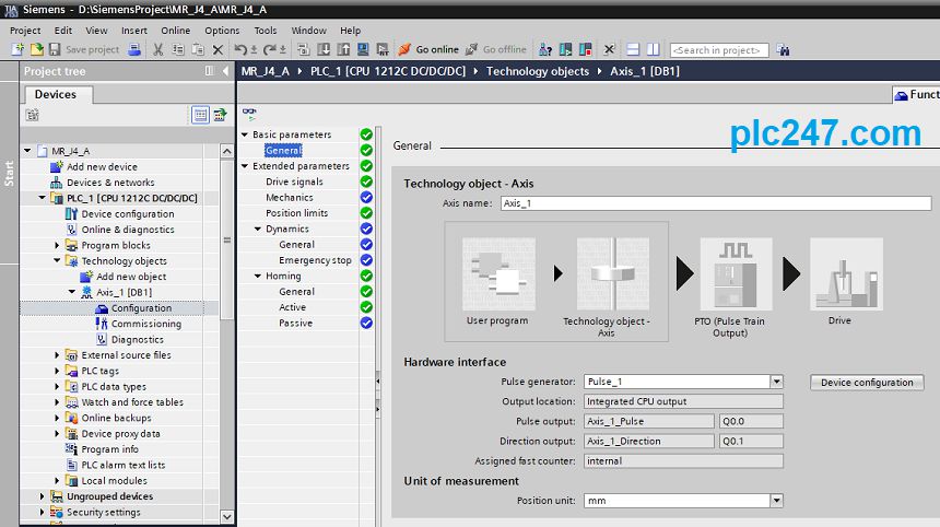
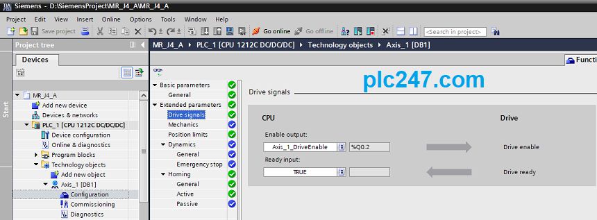
+ Extended parameters


+ Dynamics


+ Homing


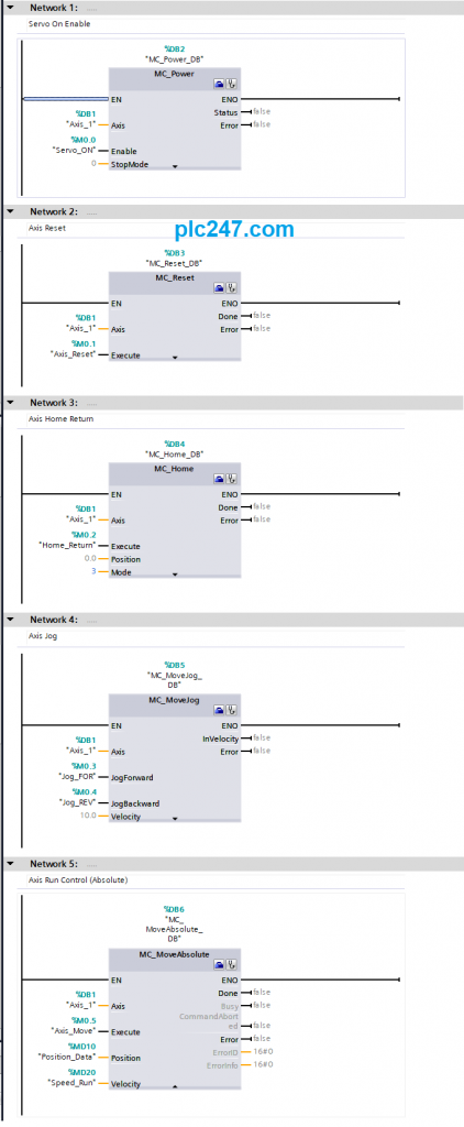
S7-1200 Servo Control Programming
This is the simplest program that can be used to control servos, you can copy this program.
Detailed Instruction Video
======
Required software and documention:
+ STEP7 & WinCC Professional V15.1 Download
+ MR-Configurator2 for MR-J4-A Parameters Setup
If you have any questions, need plc247.com’s support in connecting Siemens S7-1200 with Mitsubishi MR_J4_A, please comment below the article.
Thanks and Best Regards!


Hi Admin
in the actual sir 3 position and Automatic you have a sample sir with HMI Monitoring.
Merry Christmas And Happy New Year
Thank You
i will make tutorial when possible
very useful
thanks a lot
hello, You can create lecture series S7 1200 control Inverter Mitshubishi via Rs 485, Please!
searh on my website have
hi sir,
any changes drive hardware configurations v15 & v17
no need changes anything
hello sir, great tutorial, I have questions, why we put resistor 2K2 on output plc?
Reduce 24VDC to 5VDC sir