

In the previous post, plc247.com showed you how to use PLC S7-1200 to communicate Modbus-RTU with LS-iG5A inverter.
Today I would like to continue to share with you the S7-1200 PLC connections with Yaskawa-V1000 inverters using the S7-1200 CB1241 RS485 Module
S7-1200 CB1241 Connection Diagram with LS iG5A
Please connect according to the following diagram:

Yaskawa V1000 Inverter Parameter Setting
You set the parameters according to the table below

Register Address Write Command

>>> Motor Control Run Address = 40001 + 1 = 40002 (dec)
+ Set 40002 = 0000.0000.0000.0001 (Bin) = “1” >>> Forward Run
+ Set 40002 = 0000.0000.0000.0010 (Bin) = “2” >>> Reverse Run
+ Set 40002 = 0000.0000.0000.0000 (Bin) = “0” >>> Stop
>>> Motor Frequency Write Address = 40001 + 2 = 40003 (dec)
Register Address Data Response

>>> In the project I use the instruction to read feedback data from the inverter 3 consecutive registers will start with address:
First Address Read = 40001 + 36 (24Hex) = 40037 (dec)
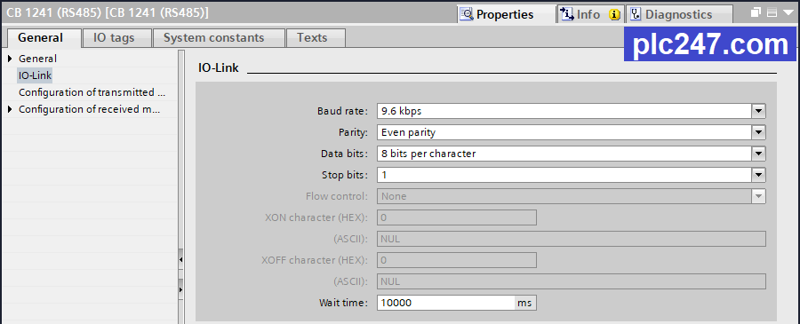
S7-1200 CB 1241 Configurator
Modbus Block Creat

S7-1200 Write Programs
+ Read and Write Distribution

+ Communication Configurator

+ Frequency Write

+ Control Run Command

+ Data Output Read

Video Tutorial
======
Document and Software:
- Download Yaskawa V1000 VFD Manual PDF (Password: plc247.com)
- Download Tia Portal V15.1 for PLC S7-1200
Thanks and Best Regards!


really i wana to say thank you
Hello good time
Thanks for the tutorials you put on your site
I am having trouble communicating between 5 Yaskawa drives and a Siemens PLC 1200 via Modbus protocol, I hope you can help me.
I have managed to establish a connection, but I have a problem. Unfortunately, the connection between the PLC and the drives is interrupted while the system is working, and a CE alarm appears on the drives.
I have checked the solution to fix this problem of the earth system and I don’t know what is the reason for this error
You should use a 120Ω terminal resistor at the inverter no.5