

The Allen-Bradley MicroLogix 1400 PLC is an extremely powerful upgrade of the MicroLogix 1100 PLC. It is integrated with many higher level functions such as built-in RS232, RS485, Ethernet IP, Analog Input/Output…
Today plc247.com will guide you to use the MicroLogix 1400 PLC to control the Stepping Motor in the simplest and easiest way.

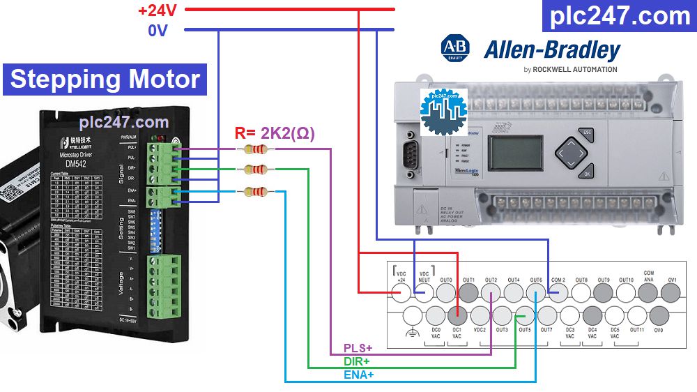
MicroLogix 1400 & Stepping Motor “Wiring Diagram”
Note: Project uses Model MicroLogix 1400 1766-L32BXB (1766-L32BXBA same)
+ R= 2K2Ω: Reduce voltage from 24VDC to 5VDC
+ DM542 Setting 1000PLS = 1 Rev.
PLC MicroLogix1400 “Pulse Train Output” Setting
+ Note: Default OUT-Output parameter will be -1, we need to change it to 2 or 3 or 4 (Output 2,3,4) otherwise PLC will report an error

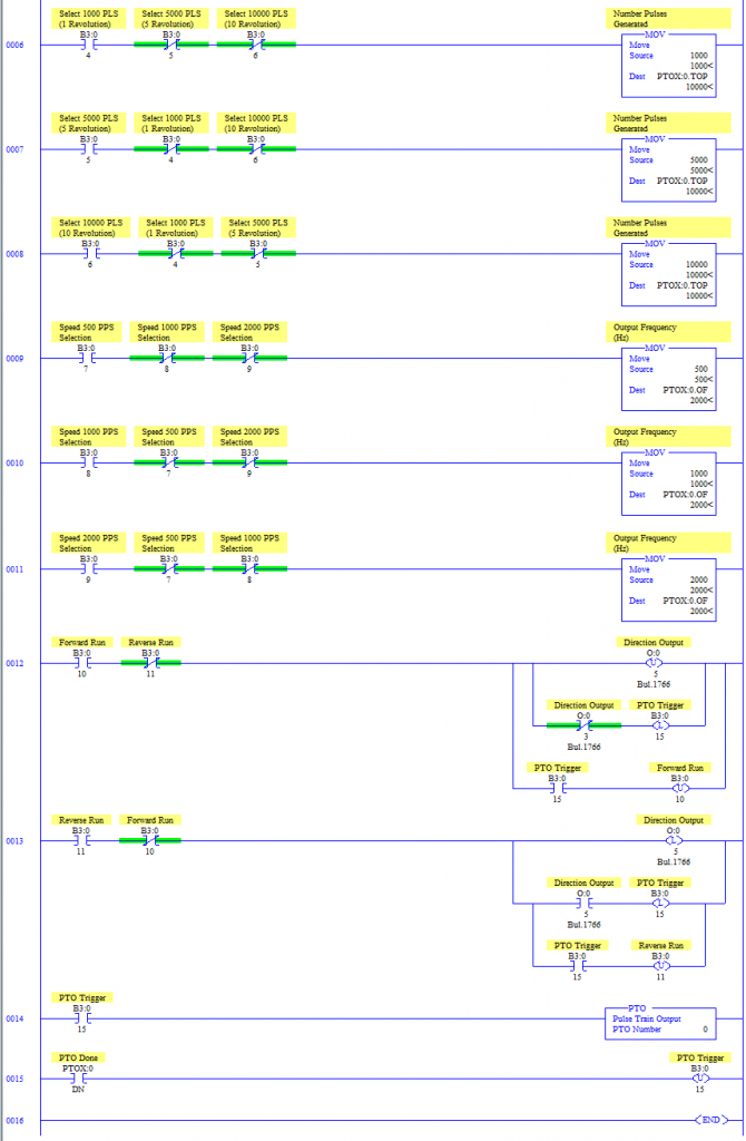
PLC Programming
+ Step ON/OFF & Jog Process

+ MicroLogix Possition Control
Project Video Tutorial
======
Please share the article to the community if you find it useful, subscribe to Youtube channel and Website to read new articles of plc247.com
Thanks and Best Regards!


